

How GNSS reflectometry works
Questi contenuti non sono ancora disponibili nella tua lingua.
A short, non-mathematical explanation for operators, followed by the details an installer needs. Sources are listed in Sources.
The idea in one paragraph
Section titled “The idea in one paragraph”Navigation satellites (GPS, Galileo, BeiDou, GLONASS) continuously transmit radio signals in the L band (about 1.6 GHz, a wavelength of 19 cm). A GNSS antenna near a lake receives each signal twice: directly from the satellite, and reflected by the water. The two copies travel different distances, so they add up or cancel each other depending on their phase difference. As the satellite rises or sets, that difference changes, and the signal strength recorded by the receiver (the signal-to-noise ratio, C/N0) oscillates. The rate of the oscillation depends on how high the antenna is above the water: the higher the antenna, the faster the oscillation. Measuring that rate gives the antenna–water distance, the reflector height (RH). When the water rises, RH decreases; when it falls, RH increases. This technique is called GNSS Interferometric Reflectometry (GNSS-IR). The home page has an interactive simulation of it.
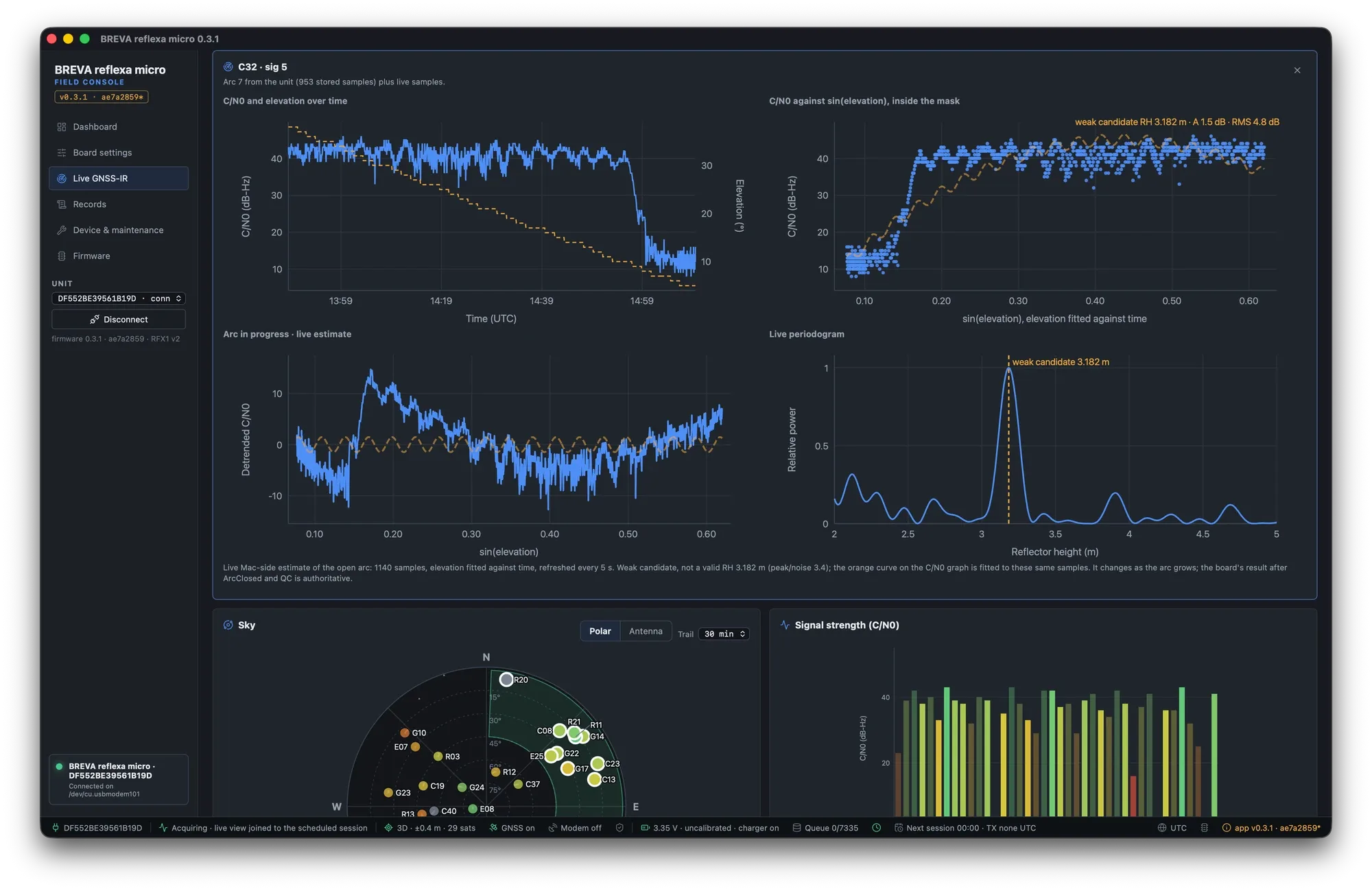
Field console, arc inspector during a test session: C/N0 of one satellite over time (top left) and against sin(elevation) (top right); the detrended oscillation (bottom left) and its periodogram with one clear peak at the reflector height (bottom right).
Why it works with a cheap antenna
Section titled “Why it works with a cheap antenna”Geodetic antennas are designed to reject reflections (“multipath”). A small patch antenna such as the one in the reflexa micro receiver rejects them less, so the interference is stronger and easier to see. GNSS-IR uses only the signal strength from a single antenna: no second antenna pointed at the water, no contact with the water, no calibration of the receiver clock.
From signal strength to water level, step by step
Section titled “From signal strength to water level, step by step”-
Select the useful signals. Only satellites low over the water are used: inside the azimuth sectors that point at the water and inside the elevation window (typically 5° to 45°). Geodetic antennas suppress the reflection above 25–30°; with the low-cost patch antenna of reflexa micro it stays visible up to about 45°, which gives longer arcs and more of them.
-
Follow each satellite pass as an “arc”. A rising or setting satellite sweeping the elevation window produces one arc; with GPS, Galileo or BeiDou an arc takes roughly 40–90 minutes.
-
Remove the direct signal. The slow trend of C/N0 with elevation is removed with a low-order polynomial; what remains is the oscillation.
-
Find the frequency. In the variable sin(elevation) the oscillation has a constant frequency equal to 2·RH/λ (λ = 19 cm for L1). A Lomb–Scargle periodogram (a spectral analysis suited to unevenly sampled data) finds the dominant frequency; RH = frequency × λ / 2.
-
Check the quality. One clear peak well above the noise, enough samples, enough elevation span, a frequency inside the expected range: otherwise the arc is rejected with a reason (shown in the app).
-
Combine. Accepted arcs of a session are combined into one robust session estimate (weighted, with outlier rejection), with its spread.
reflexa micro does all of this on the board, as the arcs close, and stores one result per arc plus the session estimate. The field console repeats the same analysis on the computer while you watch (the “provisional preview”), and adds a wavelet scalogram to see how the frequency changes along an arc. What limits the precision is explained in Precision.
Real arcs are not always clean: automatic jump detection
Section titled “Real arcs are not always clean: automatic jump detection”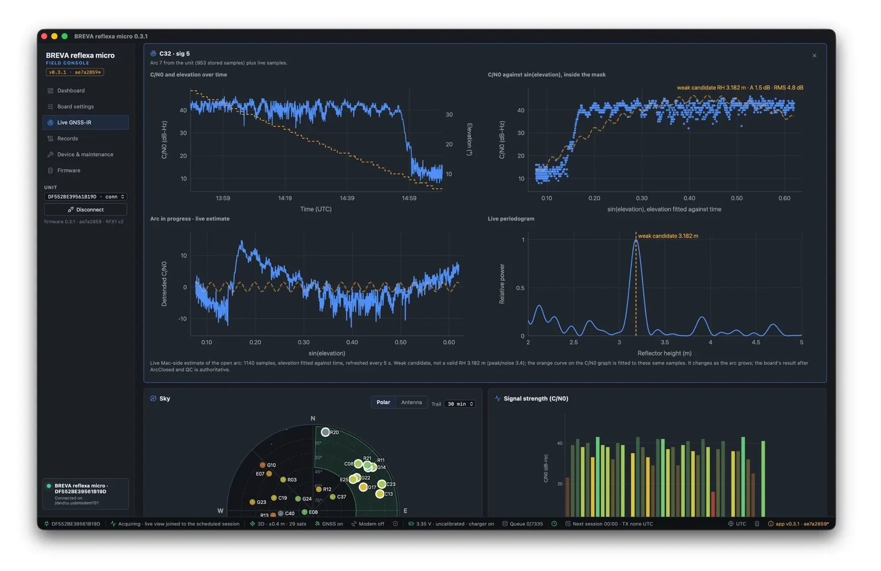
Test session, satellite C32 (BeiDou), before automatic jump detection: at the end of the setting pass C/N0 falls abruptly from about 40 to 10–15 dB-Hz (receiver losing lock, low elevation). The flat low block bends the polynomial detrend (bottom left), so the live estimate was only a weak candidate (RH 3.182 m, peak/noise 3.4) for an antenna about 3.20 m above the water.
A pass can contain portions that carry no reflection signal: a block of very low C/N0 when the receiver is losing (or not yet locking) the satellite, or weak lateral multipath before a coherent signal. Left in, they distort the detrend and the periodogram. reflexa micro detects these abrupt, persistent level jumps automatically:
- On the unit: a conservative trim removes persistent low-C/N0 blocks at
either edge of an arc (acquisition or loss) before the analysis. The raw
arc is kept, and the result is flagged
ROBUST_TRIMMED. - In the field console: the jump is gated before the detrend, and a wavelet analysis (the BREVA++ continuous wavelet transform) selects the coherent part of the arc. The inspector shows the retained and rejected ranges, the reason for the cut, and a periodogram computed from exactly the retained samples; the untrimmed samples stay available.
- Result on the C32 case (simulated replica of the 953-sample pass): 840 samples retained, RH 3.16 m for a 3.20 m truth.
Where the reflection happens (the footprint)
Section titled “Where the reflection happens (the footprint)”The reflection comes from an elongated area of the surface (the first Fresnel zone), centred at a distance from the antenna that depends on the antenna height and on the satellite elevation. Low satellites reflect far away, high satellites close to the antenna:
| Antenna height above water | Elevation 5° | 10° | 20° |
|---|---|---|---|
| 2 m | centre ~35 m, length ~54 m | ~15 m, ~18 m | ~6 m, ~6 m |
| 5 m | ~70 m, ~80 m | ~32 m, ~28 m | ~15 m, ~10 m |
| 10 m | ~127 m, ~110 m | ~60 m, ~39 m | ~28 m, ~14 m |
(L1, first Fresnel zone; width a few metres.) The field console draws the footprint and the Fresnel zones on the map for your sectors and elevation window, and shades the parts hidden by terrain (indicative: the terrain model has no buildings or vegetation, see obstructions).
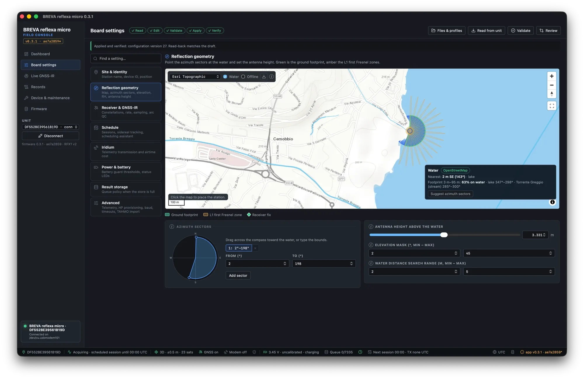
Settings → Reflection geometry: azimuth sector toward the lake, ground footprint (green) and first Fresnel zones, water detected from the map (test site on a lake).
Which sites give a good footprint is covered in Site requirements.
Beyond water level
Section titled “Beyond water level”The same physics measures snow depth (the snow surface is the reflector) and soil moisture (the phase and amplitude of the oscillation change with the water content of the soil). These belong to the wider BREVA processing software; a reflexa micro unit measures water level only.