Hardware
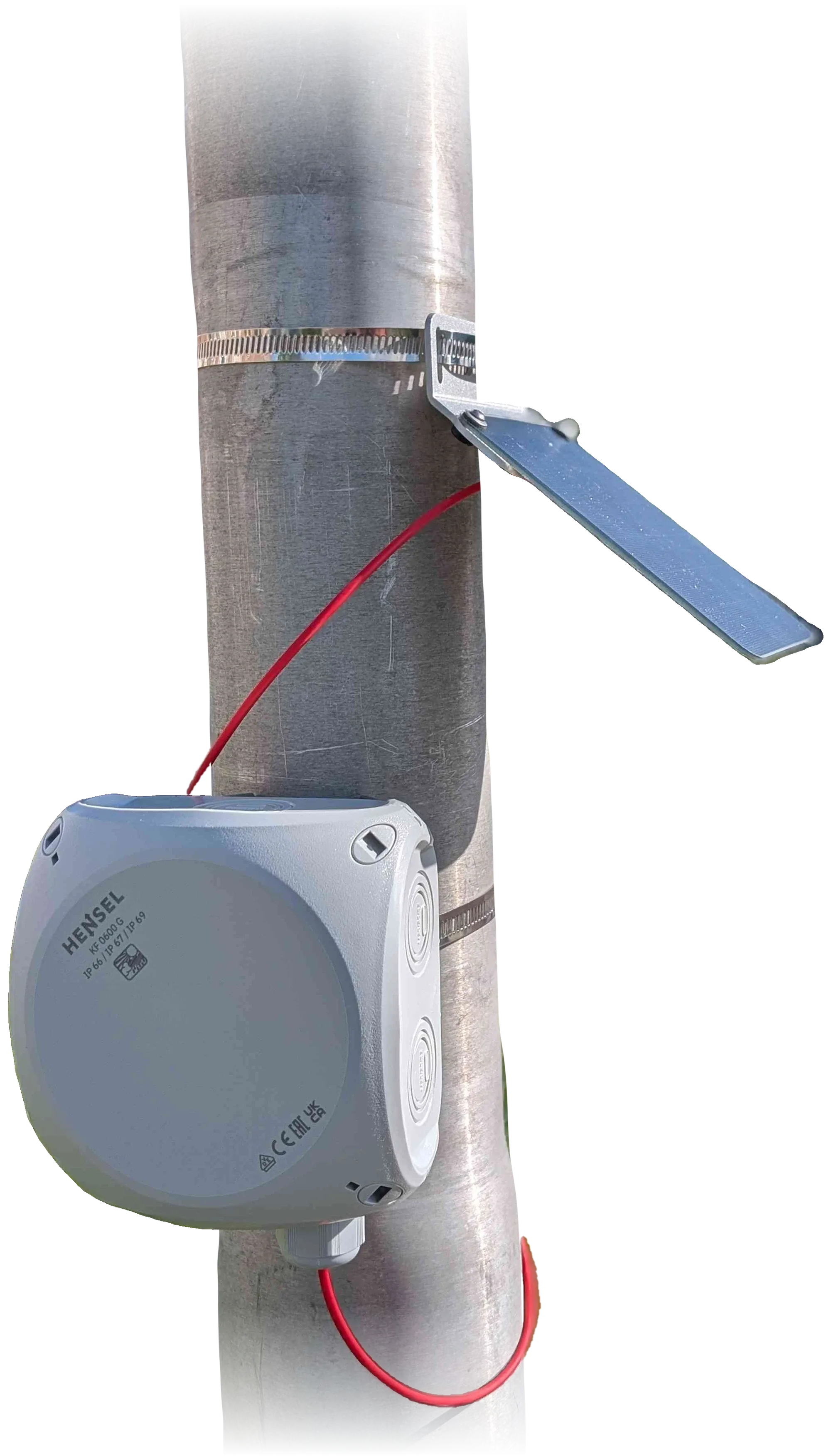
The unit installed on a pole: the solar panel on its bracket, the enclosure and the red solar cable to the cable gland.
Photo: TAHMO WLM.reflexa micro runs on the TAHMO WLM V1 board. The same board runs TAHMO’s own firmware (“Tiger”); reflexa micro replaces that firmware with its own. The board revision of the units in the field is not yet confirmed against the schematics, so pin assignments are taken from the schematic and are marked as such in the engineering documents.
Where the hardware comes from
Section titled “Where the hardware comes from”The unit comes from TEMBO Africa, an EU Horizon Europe project that develops in situ monitoring of weather and water in Africa, in which TU Delft, TAHMO and GReD are partners. The hardware is the low-cost, flood-proof GNSS-IR water-level gauge designed by TU Delft and built by TAHMO as its WLM, also known as TIGIR (“Tiger”), presented at the EGU General Assembly 2026 (van de Giesen et al., EGU26-75): reflectometry processed on the board, so that only the water level and a few health values travel over a small satellite modem.
Within the project, GReD develops the software: the reflexa micro firmware and the field console. The board, the enclosure, the assembly and the photos and diagrams credited “TAHMO WLM” are TU Delft’s and TAHMO’s work. This site documents the reflexa micro software and the units that run it; TAHMO distributes its own version of the unit, with its own firmware and documentation.
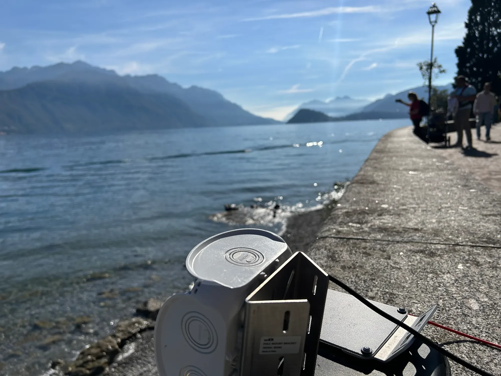
Test installation: the unit and its bracket on a lake-side wall over the water.
Main components
Section titled “Main components”| Function | Part | Notes |
|---|---|---|
| Microcontroller | Raspberry Pi RP2350A (QFN60, revision A4) | Dual Cortex-M33; firmware in Rust; secure boot image format |
| Flash | Winbond W25Q32 (4 MiB) | Code, two configuration copies, two system-state copies, result queue |
| GNSS receiver | u-blox SAM-M10Q | Integrated patch antenna; UART at 115,200 baud; switched supply (cold start at every power-up: the receiver has no backup battery) |
| Satellite modem | Ground Control RockBLOCK 9704 | Iridium IMT (“Certus” data); 5 V boost supply; supercapacitor charged at power-up (~40 s, peak ~4 W) |
| Battery | LiFePO4 26650 cell, ~3,000 mAh | Rests at 3.2–3.3 V for most of its capacity; nearly empty below 3.0 V |
| Charger | TI BQ25176M (3.5 V, 500 mA) | From solar panel or USB; charging disabled below 0 °C and above 60 °C |
| Battery monitor | LTC2960 | Disconnects the system below ~2.5 V and reconnects above ~3.1 V; low-battery flag |
| External watchdog | TI TPL5010 (~60 s) | Resets the processor if the firmware stops servicing it |
| Status LEDs | Red, green, blue | See Status LEDs |
| Power switch | Toggle switch | Switches the unit on and off; when on, the green LED blinks every 5 seconds. Charging from the solar panel or USB works even when the switch is off |
| USB | USB-C | Serial link to the field console; firmware update through the RP2350 bootloader (BOOT button) |
LiFePO4 cell ─ reverse-polarity protection ─ power switch ─ low-battery cut-off ─ VSYSVSYS ─ buck-boost (always on) ─ 3.3 V ─ processor, flash, watchdog3.3 V ─ load switch (firmware) ─ GNSS receiverVSYS ─ 5 V boost (firmware) ─ Iridium modemSolar / USB ─ charger ─ battery- The firmware switches the GNSS receiver and the modem on only when needed, and never both at the same time (current peaks, and the Iridium transmitter would blind the receiver).
- A battery guard keeps the modem off on a low battery and both radios off on a critical battery; thresholds are set in Settings → Power & battery (starting values for 1-cell and 4-cell LiFePO4 packs).
- The battery voltage shown by the app is uncalibrated (resistor divider, a few percent of error).
Energy budget (estimates, not yet measured): GNSS receiver on ~15 mA; modem start-up ~1.5 A for ~40 s per transmission; processor several mA between tasks. A day of 4 × 30 min sessions and 4 transmissions is roughly 220 mAh, dominated by the processor floor until deep sleep is implemented. The app’s scheduling assistant shows the expected consumption, autonomy and storage for the chosen schedule. Measuring the real consumption is an open qualification task.
- Reverse polarity of the battery or the solar panel is blocked by a protection circuit and shown by an LED.
- Operating temperature: −20 °C to 60 °C (TAHMO figure); the charger stops below 0 °C, so the solar panel does not charge in frost.
- Without the solar panel the unit runs for more than two days (TAHMO figure; reflexa micro’s own autonomy depends on the schedule, see the app’s scheduling assistant).
- Charging over USB needs a solder bridge on the USB Charge pads of the board (Assemble the unit); there is no indicator for USB charging.
Storage
Section titled “Storage”The 4 MiB flash holds the firmware (2 MiB), two copies of the configuration and two copies of the system state (so a power loss during a write never corrupts them), and the result queue (~7,300 records, each up to 10 arc results). Policy when full: keep the newest (overwrite the oldest, recommended) or keep the oldest. Records are removed only when downloaded over USB, cleared on purpose, or overwritten; sending them over Iridium only marks them as sent.
Watchdogs and recovery
Section titled “Watchdogs and recovery”- An internal watchdog (2 s) and the external TPL5010 reset the processor if the firmware stops making progress; the next boot records why (reset reason, hang record with the code location) and the LEDs show it for a minute.
- A requested reboot (including every firmware update) first ends the running session cleanly and saves all results still in memory.
- A Campaign interrupted by a watchdog or brown-out resumes instead of stopping (at most two recoveries per power-on).
Building a unit from the kit is covered in Assemble the unit, installing reflexa micro on a new board in First installation, mounting in Install on site; the LED patterns in Status LEDs.